| Japanese | English |
15th LSI Design Contests・in Okinawa Design Specification - 4-1-2
4-1-2. FFT circuit : N=8
(1) Circuit design
As in the case with N=4, design block diagram from the algorithm of 8-point FFT.
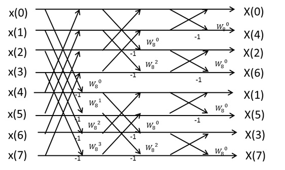
Figure 14: Algorithm of 8 point-FFT
Following the algorithm, 12 of the Butterfly computation circuit construct the N=8 FFT circuit.
Figure 15 shows block diagram.
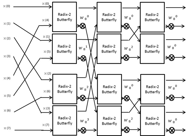
Figure 15: Block Diagram of 8 point-FFT
The designed circuit is shown in figure 16.
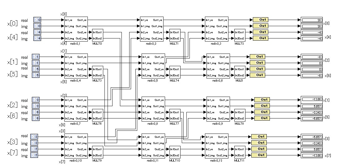
figure 16: 8 point FFT circuit for parallel input
We omit the description of subsystems radix2_1-radix-2_12, because they have the same circuit construction as the subsystem radix-2_0 in figure 6.
We also omit the description of subsystems MULT0-MULT11, because they have the same circuit construction as the subsystem MULT in Figure 7, except for the parameters of constant block.
The parameters of constant block in MULT0-MULT11 are shown in Table 3, where the twiddle factors are
![]() 、
、
![]() 、
、
![]() 、
、
![]()
Table 3: Parameters of twiddle factors
On MULT3 and MULT9 in Table3, we set 0.7071 as a round number for
(2) Notes about fixed-point arithmetic
The bit width of constant blocks of the subsystem MULT is 16-bit, and the fractional bit is 14-bit.
![]() can be expressed as 0.70709228515625 by the fractional bit.
can be expressed as 0.70709228515625 by the fractional bit.
If we design circuits with floating-point arithmetic, the scale of circuits becomes very large. Therefore, fixed-point arithmetic is generally used for calculations. However, in this case, error occurs due to constraints on bit width.
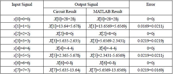
(3)Verification
In figure 9, we simulate the behavior of the circuit. The input signals are x(0)=0+0j, x(1)=1+1j, x(2)=2+2j, x(3)=3+3j, x(4)=4+4j, x(5)=5+5j, x(6)=6+6j, x(7)=7+7j , then the output signals become X(0)=28+28j, X(1)=-13.64+5.678j, X(2)=-8+0j, X(3)=-5.635-2.365j, X(4)=-4-4j, X(5)=-2.3650-5.678j, X(6)=0-8j, X(7)=5.635-13.64j, and Input to Output latency of this circuit is 0.
The difference between the result of circuit simulation and MATLAB simulation is shown in Table
The error range is about ![]() , and the cause of this error is rounding error which occurs by expressing
, and the cause of this error is rounding error which occurs by expressing ![]() in binary at constant block of MULT.
In order to do more accurate calculation, we need larger bit width for fractional bit of constant block in the subsystem MULT.
in binary at constant block of MULT.
In order to do more accurate calculation, we need larger bit width for fractional bit of constant block in the subsystem MULT.
Table 4: The difference between the result of circuit simulation and MATLAB simulation