Design Specification
1.Small RISC Processor
(SRP) architecture
5.Instruction ROM and
Data Memory
BASIC
FREE
12th LSI Design Contests・in Okinawa Design Specification - 1
1.Small RISC Processor(SRP) architecture
Figure 1 shows the design target SRP architecture. This architecture is of course not original. Just 9 instructions are extracted from the RISC computer in the book “COMPUTER ORGANIZATION & DESIGN: the hardware / software interface” by Professors Hennessy and Patterson. Then the SRP also have a feature of RISC computer such as 32 bit width x 32 word Register file.
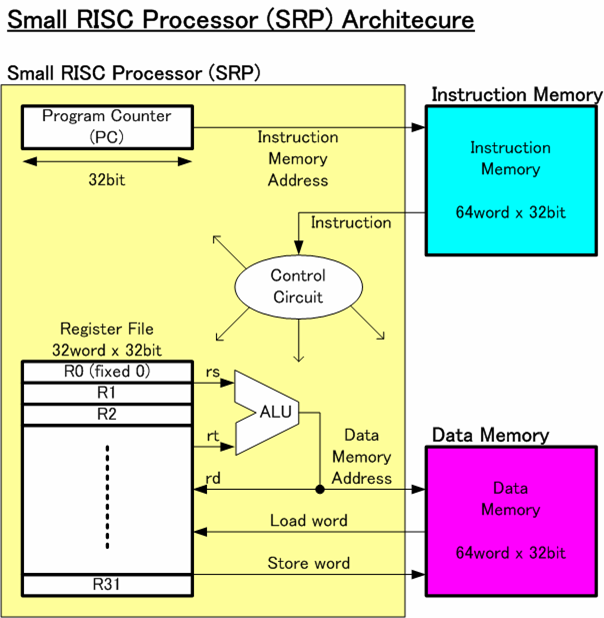
Figure Small RISC Processor(SRP) Architecture
Figure 1 consists of SRP and two memories. The design target is SRP. However, in order to run some computer program, instructions and data are essential. In this architecture, two separate memories are used for both instructions and data. This independent memory architecture also simplifies the design of SRP.
Instructions are all 32 bit width. We call 32 bit as a Word. Those 32 bit instruction Words are stored in the instruction memory. The SRP reads out the instruction from the instruction memory one by one and execute the instruction.
The operation can be divided into the 4 stages.
Stage 1: instruction fetch
32 bit program counter in SRP indicates the address location of the target instruction in the instruction memory. SPR reads out the target instruction according to the PC.
Stage 2: instruction decode
Before analyzing the read-out instruction, SPR does not know the contents of the instruction. Then SPR decode the instruction. According to the result of the decoding, SRP controls the other functional block in the SRP such as Arithmetic Logic Unit (ALU), Register File (RF) and Program Counter (PC).
Stage 3: execution and memory access
According to the stage 2 decoding, RF data will be read out if needed. ALU will compute if needed. Data memory will be accessed (read or write) if needed
Stage 4: write back
At the final stage, stage 3 ALU results or Data memory output will be transferred to Register File. The next PC value will be calculated to go back to Statge1.
By repeating those four stages, computer can perform operation.
Reference 1: refer to the section 5.1-5.3 of Morgan Kaufmann Publisher,
"COMPUTER ORGANIZATION & DESIGN: the hardware / software
interface 2nd", John L. Hennessy and David A. Patterson