| Japanese | English |
Design Specification
1. Noise Cancelling Algorithm[1]1-1. Specter Subtraction Method (SS Method)
2. Implementation of the Noise Cancelling System
2-1.Separating into the Hardware and the Software
2-1-1.Features of the HW and the SW
2-1-2. Feature of Noise Cancelling System
2-1-3. Architecture
2-2. Hardware
2-2-1. Processing flow
2-2-2. Circuit structure
2-2-3. HW timing
2-3. Software
2-3-1. Source code
2-3-2. Flow chart
3. Development Environment
3-1. Hardware Design Process
3-1-1. Design Hardware Logic
3-1-2. Manual of Xilinx ISE and EDK
3-2. Software design process
4. Contest Design Target
5. SPEED and AREA
6. References
7. Download
16th LSI Design Contests・in Okinawa Design Specification - 1
1. Noise Cancelling Algorithm[1]
To remove noise, there are some methods are suggested such as Microphone Array Method which is used several microphones and method using adaptive filtering to presume unknown pathway. In this simulation, the Noise Cancelling System by using Specter Subtraction Method (SS Method) which removes the noise in frequency domain is targeted.
1-1. Specter Subtraction Method (SS Method)
In this section, the Noise Cancelling Algorithm is explained. The algorithm removes the noise in frequency domain. A diagram of the Noise Cancelling Algorithm is shown in Figure 1.
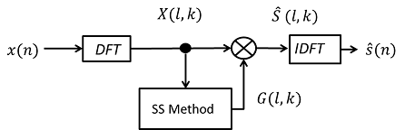
Figure 1
First, the observed signal is assumed to be given by the sum of speech and noise. The observed signal, the speech and the noise at time n are defined as x(n), s(n) and d(n) respectively. Then, the observed signal x(n) is expressed by
when the speech and the noise are uncorrelated.
Next, to remove noise in frequency domain, the Discrete Fourier Transform (DFT) applies the observed signal x(n). After that, the observed signal specter X(l,k) from top to k in l-frame is expressed by
when S(l,k) and D(l,k) denote the speech specter and the noise specter respectively.
The estimate value of speech ![]() is expressed by the observed signal specter X(l,k) as.
is expressed by the observed signal specter X(l,k) as.
Here, G(l,k) is a specter gain, and the estimate value specter is result of the observed signal specter X(l,k) multiplied by suitable specter gain G(l,k).
The ideal estimate value ![]() is expressed by
is expressed by
By substituting eq.(4) into eq.(3), the ideal specter gain G_opt (l,k) given as.
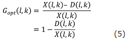
Then, the speech specter X(l,k) is extracted perfectly. However, the noise specter D(l,k) can’t be obtained by only the speech specter X(l,k)’s
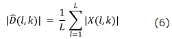
information. Therefore, for SS Method, the noise specter estimate value ![]() can be obtained by using the ‘L’ number of frames in non-speech interval.
can be obtained by using the ‘L’ number of frames in non-speech interval. ![]() is defined as
is defined as
The simulation of the SS method was performed by Scilab. The result is shown in Figure 2. We can download the program (here).
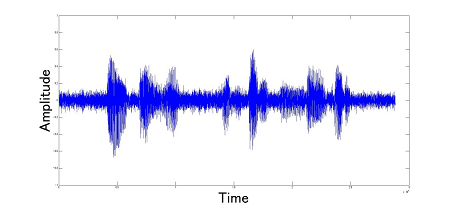
(a)Input Signal
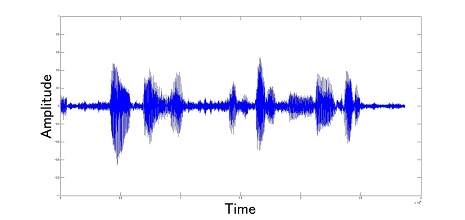
(a)Output Signal
Figure 2